Milight smart lightbulbs, aka LimitlessLED bulbs, are cheap Smart ‘WiFi’ lightbulbs. They require a Milight hub to connect to WiFi however. These hubs are known to be a bit shit. They require the shit Milight app to configure them, and also only allow a max of 4 RGB groups, 4 RGBW groups, 4 CCT groups… This is a massive hindrance if you have more than 4 rooms/zones containing RGBW lights for instance. You then have to buy another Milight hub to give you more groups and they’re about £30 each.
Wouldn’t it be nice if there was a hub that you could connect as many Milights to as you want in as many groups as you like that only cost about £5 in parts? That’s where Chris Mullins’ fantastic Milight WiFi gateway emulator comes in. The below is my finished version. It’s not pretty, but it’ll sit out of sight and I could find a box to put it in if I wanted to.

References for this post:
https://github.com/sidoh/esp8266_milight_hub
https://github.com/sidoh/esp8266_milight_hub/wiki
https://github.com/sidoh/esp8266_milight_hub/wiki/Troubleshooting
https://github.com/sidoh/esp8266_milight_hub/wiki/HomeAssistant
Guide
I followed Chris’ guide, which is great, but kinda meant for electronics people who play around with Arduino boards and know what they’re doing. This took me a whole day of trial and error to figure out and get working from his guide and then learning the bits Chris skips over. I have never touched an Arduino before yesterday which was part of the battle. I hope this helps other noobs like me out there.
I am using Linux (Pop_OS!) not Windows, so the steps you take if using Windows may deviate from the steps below somewhat, but the general gist and concepts will be the same. I couldn’t get the standard way (in Linux) to flash the firmware to work, so opted for the PlatformIO method as recommended by Chris. If you want a simpler method on Windows, try downloading and flashing the latest pre-compiled firmware binary and flash using the NodeMCU-flasher as described in Chris’ blog. You may find it simpler and quicker than the way described below with PlatformIO.
Parts
Total parts (listed on Chris’ guide linked above) were about a fiver from AliExpress.com. They take a month or so to arrive, but they’re super cheap.
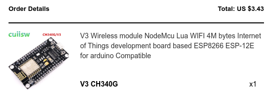
- NodeMCU v3: “V3 Wireless module NodeMcu Lua WIFI 4M bytes Internet of Things development board based ESP8266 ESP-12E for arduino Compatible” (it said CH340G on the order, but came with CH340C written on the chip. ‘C’ is a crystal something or other, better?) – This is the control board that plugs into the power from a MicroUSB cable. It has an onboard ESP8266 WiFi chip which is a defacto standard in these types of projects. It looks like Chris has configured the project for WEMOS D1 Mini also, so think that might be an option, and even cheaper than the NodeMCU. There’s also the newer NodeMCU ESP32 which is more powerful but not sure if that’s supported, or indeed if that’s overkill.
- NRF24L01: “Wireless Transceiver NRF24L01+ 2.4GHz Antenna Module NRF24L01+PA+LNA 1000 Meters”. This is the 2.4Ghz transmitter that talks to the lights.

- Dupont connectors – the key point here is that they’re Female to Female and relatively short. The pack I got had a range of lengths and types. These are the wires that connect the pins on the NodeMCU to the transmitter module.

Plug the boards together
This is the easiest part of the project. No soldering required. Use the Dupont connectors to connect the two boards together as per Chris’ guide.
Drivers
Half way through attempting to install the drivers, and failing, I found I didn’t need to install drivers… I use Linux and I read that drivers to connect to the NodeMCU are already part of the OS so the PC can natively talk to the NodeMCU once it’s plugged into a USB cable. You may need the drivers if you’re on a Windows PC. They’re listed on Chris’ page.
I can’t remember if the following python and tools install were part of my attempt to install the drivers or not, I got so lost going round and round in circles for 4 hours. You might need them. If you’re on Windows you’ll definitely need to follow Chris’ guide links to installing drivers. I think this was when I was trying the manual install method before trying the PlatformIO method, which is too easy when you know how to actually use it (full noob-level details later in this guide!):
sudo apt-get install python
sudo apt-get install python-setuptools
Installing Firmware
The firmware is the program that Chris created that you need to install on the NodeMCU board.
Plug in the board to a microUSB connected to your PC. the blue light should flash momentarily. To see if it’s being recognised correctly you can run:
sudo dmesg
Somewhere in the lines that are returned you should get a couple of lines that look like the below.
[90468.656209] ch341 3-4:1.0: ch341-uart converter detected
[90468.656782] usb 3-4: ch341-uart converter now attached to ttyUSB0
‘CH341’ is the onboard chip and ‘ttyUSB0’ is where it’s connected on your PC. I
Install VSCode. This is Microsoft’s code editor. It’s very good. I use it every day at work.
Inside VSCode, install the extension called PlatformIO.
Overview of PlatformIO: https://www.youtube.com/watch?v=0poh_2rBq7E&t=349s
PlatformIO – install in VSCode: it’s installed from the Extensions area (the 4 squares), and after installing it will be available in the icon on the bottom left that looks like an alien bug:

Within PlatformIO I clicked New project, chose the NodeMCU 1.0 (ESP-12E Module) because my AliExpress order listed ‘ESP-12E’, and Arduino as the Framework.
In the New Project box, select the board, and Arduino as the platform.

I named my project NodeMCU2ndAttempt as I cocked up on the first try.
On the ‘Board’s page, choose NodeMCU v2 (even though the board is a v3).

In the project window, right click the project folder and ‘open containing folder’.
From the Github project page (linked above), download the zip file and extract it into the main project folder you just opened. Your project folder should now look like the above screenshot showing the list of files.

When I extracted/moved the files I didn’t have hidden files visible (Ctrl+H on Linux); this missed several files and then caused the next steps to fail, hence my second attempt.
Now you’re ready to build the project and install onto the NodeMCU.
First click the checkmark icon on the bottom left of the VSCode/PlatformIO window. This will build the project ready to go onto the NodeMCU. It will take a while to complete.

After it has completed, you hopefully will see several lines of green code that say something like ‘Success’.
Once you’ve seen success, click the Right facing arrow on the bottom of the window. This will start transferring the data to the NodeMCU. The blue light on the board will flash like crazy whilst it’s doing this.
If you get an error about no access… run the following command to set the write permissions on the NodeMCU
sudo chmod a+rw /dev/ttyUSB0
Once it completes, you should again see some Success messages. I think the one that matters is the ‘nodemcuv2’ line:
nodemcuv2 SUCCESS 00:00:22.308
I saw an error on one of the lines… but think it was for another type of board and didn’t seem to make a difference:
nodemcuv2 SUCCESS 00:00:22.308
d1_mini SUCCESS 00:00:22.537
esp12 FAILED 00:00:13.752
esp07 SUCCESS 00:00:24.281
huzzah SUCCESS 00:00:26.478
d1_mini_pro SUCCESS 00:00:22.661
Another time I tried it, a different error:
nodemcuv2 SUCCESS 00:00:21.578
d1_mini SUCCESS 00:00:22.729
esp12 SUCCESS 00:00:22.661
esp07 SUCCESS 00:00:22.769
huzzah SUCCESS 00:00:22.768
d1_mini_pro FAILED 00:00:13.825
Once complete, unplug and replug microUSB cable into the NodeMCU. After 10 to 20 seconds you should get a steady slow blue flash from the NodeMCU board. I guess the ‘RST’ button on the NodeMCU does the same, but not tried it. Not sure what the other button ‘FLASH’ does, maybe something to do with flashing the storage like we did above?
From your phone/laptop, search for a new WiFi network SSID named ESPxxxxxxxxx and connect to it. The password is ‘milightHub’.
Go to the login webpage (should pop up as ‘sign in to this network’ option) and use this to connect the device to your main WiFi network…
It looked very much like this if I recall… can’t remember WiFi option I chose… probably Configure WiFi:

Connect to your normal WiFi network, with the password for your SSID. The MiLight Hub main configuration page should then be available on your normal network (see next screenshot). You will see that your phone/laptop has disconnected from the ESPxxxxxxxxx network as it will no-longer be available. Also from the WiFi setup page you can set a static IP if you wish.
In a browser on your PC you should now be able to access the configuration page via its IP address. If you don’t know what DCHP address the NodeMCU got, check your router DHCP leases, or use a scanner like Advanced IP Scanner, or AngryIP to locate it’s address. The device hostname will show up as ‘milight-hub’

If you cock it up and want to start again
You can erase the flash memory on the NodeMCU:
sudo chmod a+rw /dev/ttyUSB0 # to set the NodeMCU as writeable
esptool.py --port /dev/ttyUSB0 erase_flash # erase
Add an existing Milight official hub
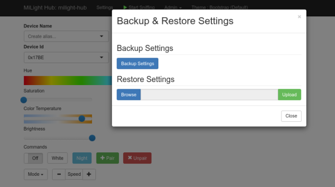
If you already have a hub set up, you can spoof it, by finding out its device id and using that. This way you won’t have to rebind your lights. Click the ‘Start Sniffing’ button and press a button on your remote from milight app. Mine showed up as 17BE.
Add this to Milight-hub in the Device ID field prefixed with 0x: 0x17BE as per screenshot above.
Pairing lights
https://github.com/sidoh/esp8266_milight_hub/wiki/Pairing-new-bulbs
Use Device ID: 0x0001 upwards. Any number is ok. This can be entered as 0x1.
- Leave the Group at 1 unless you want to put lights into groups.
- Select the Remote Type: RGBW/CCT etc as per the bulb you’re trying to pair
- Enter a device ID… just make one up. This becomes your logical hub (each Device ID is the equivalent of an official physical Milight hub… took me a while to figure out this concept)
- Turn the bulb off
- Turn the bulb on
- Within 5 secs, press the Pair button
- The bulb will flash on and off several times to show that it’s paired
- We’ll add an alias to the devices later, so they show up in Home Assistant
The device IDs I chose are below. I put each light in the house on it’s own logical hub (Device ID is the equivalent of a Physical Hub) to make it as simple as possible and to have each light easily controllable independently. The only ones I added multiple to were the kitchen spots. They’re currently on a single light switch that turns them all on/off:
- 0x0001 – Lounge
- 0x0002 – Kitchen spots (x4)
- 0x0003 – Kitchen table
- 0x0004 – Hall
- 0x0005 – Landing
- 0x0006 – Master Bedroom
- 0x0007 – Study
Pairing multiple lights on same switch
- Unpair them first. Turn the bulb off, then on, and press the Unpair button. The ones that are unpaired, unscrew them. Continue to unpair until they’re all unpaired
- Power off at the wall
- Screw them back in
- Do the normal pair procedure and they should all pair up to the same Device Id you choose.
Turn lights on/off from Milight Hub
- Select the device ID (this is the equivalent of the hub to choose), or the Device Name alias
- Select the Remote type to match the light type
- Select the command to run: on/off/white/night etc.
Now the lights are controllable individually from the new hub, you can add them into Home Assistant…
MQTT setup for Home Assistant
MQTT is the protocol used to communicate to the hub over WiFi from Home Assistant.
Set up the Milight Hub for MQTT
The docs refer to espMH… I assume this means ESP (the WiFi module is an ESP8266), and MH (Milight Hub).
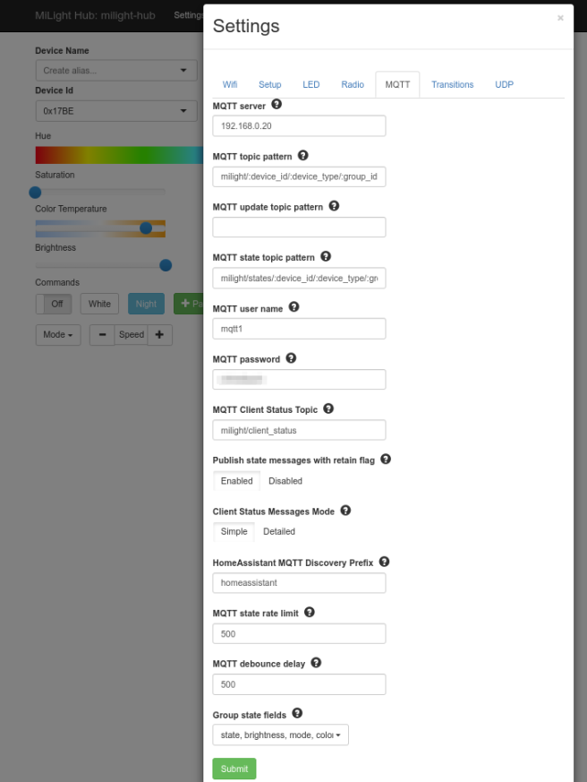
Go to Settings > MQTT in Milight Hub and add the following:
mqtt_server– your MQTT broker. can be an IP of your Home Assistant or a hostname. Specify the port here (e.g.,mymqttserver.com:1234) if it’s not the default (1883).mqtt_username/mqtt_password– if you have auth enabled on your MQTT server. These are the same as the user created earliermqtt_topic_pattern– set this tomilight/:device_id/:device_type/:group_id.mqtt_state_topic_pattern– set this tomilight/states/:device_id/:device_type/:group_id.- Optionally: set
mqtt_client_status_topictomilight/client_status, andsimple_mqtt_client_statustotrue(in the UI, set “Client Status Message Mode” to “Simple.”) - Make sure you’ve got the appropriate
group_state_fieldsselected. The default values should work: state, brightness, computed_color, mode, color_temp, bulb_mode. - HomeAssistant MQTT Discovery Prefix:
homeassistantThis should match what the configuration.yaml mqtt setting is set to later in this guide.
Set up a User in Home Assistant
-
- Configuration > Users> add a user and password
- Add a username and password. I called it mqttuser .
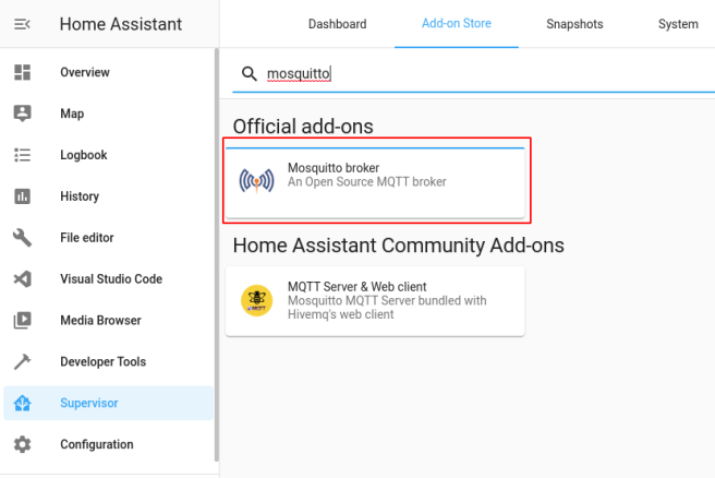
Install Mosquitto Broker Addon
- Supervisor > Addons: install Mosquitto broker
After install, if you’re using Docker you’ll see a new container:

- Enable Start on boot, Watchdog, and Autoupdate

- Start the Mosquito service (in the diagram above, the start button will be where the STOP button is
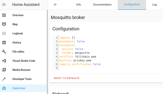
- Mosquitto Configuration tab: leave at defaults:
logins: []
anonymous: false
customize:
active: false
folder: mosquitto
certfile: fullchain.pem
keyfile: privkey.pem
require_certificate: false
Install Mosquitto Integration

- Configuration > Integrations: MQTT > Configure
- Click CONFIGURE

Broker: 192.168.0.20 (IP of home assistant)
Port: 1883 (the default)
Username: mqttuser
Password: the one set above
Add the MQTT section in configuration.yaml
In configuration.yaml in Home Assistant, add
mqtt:
  broker: 192.168.0.20 (enter the Home Assistant IP address here)
  discovery: true
  discovery_prefix: homeassistant
  username: mqtt1
  password: same password as above

Add an alias to each light so that it shows up in Home Assistant on a card
You can now add a Device Name alias to the Device Id if you want. This will show up in Home Assistant later and also make it easier to remember which device ID is which in Milight Hub.

- Select one of the Device IDs you paired earlier
- select the Device ID and group corresponding to the light you want to add
- select the Remote Type, corresponding to the RGB/W/CCT type for the light
- Enter a Device Name alias for the light, in the example above ‘stairs light’
- Click on Add ‘stairs light’
- The device should now be immediately available on the Overview page in Home Assistant
- Once you’ve added all the lights should look like this:

- and like this in Home Assistant as well as being available as entities to apply automations to
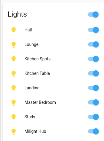
Entities are named light.hall or whatever Alias you gave them in Milight Hub:
Done.
You can override the auto-adding of the lights in Home Assistant by adding the MQTT light config to your Home Assistant manually, but I have’t got to that stage (or needed to) in my Home Assistant journey yet.
When you now toggle on/off a light in Home Assistant the NodeMCU blue light does a flicker. The on/off is instant, no lag whatsoever!
Once it’s all working, take a backup:
Thanks Chris Mullins, great project!
Further notes
From poudenes on the Home Assistant Community Forum:
I use this for a long time now… love it!!!
Be careful with the part ” Add an alias to each light so that it shows up in Home Assistant on a card”
If you add names the memory can be full and then you lost all settings of your lights.
I didn’t use it. I have 12 Device ID’s and 32 Bulbs. Some bulbs are paired on different Device ID’s
It work great. Play with the settings “Radio” to get the best out of it in your situation.
Mine are:
Packet repeats: 75
Packet repeats per loop: 75
Radio interface type: nRF24
nRF24 Power Level: Max
nRF24 Listen Channel: Min
nRF24 Send Channels: Min, Mid, High
Packet repeat throttle threshold: 750
Packet repeat throttle sensitivity: 20
Packet repeat minimum: 100
I also don’t have any delay. But somethings the settings can help to prevent some packet drops. I have now for 3 weeks a total packet drop of 36. Thats ok.
Update:
I noticed that lights wouldn’t consistently turn on/off via the motion sensors I have. I had two lights on one motion sensor and one of them would fire correctly, so knew it wasn’t the motion sensor or Home Assistant at fault.
I tried the above settings Poudenes above suggested without much luck.
After a bit of trial and error (don’t really know what I’m doing so some of these settings may not be relevant!) I found that the following gave more consistent/accurate actions, i.e. on/off.


HI There,
I read your manual. Very nice… My hub is running for 2 years now. I see only a difference in 1 MQTT line.
My hub namme is: Milight_Hub
MQTT state topic pattern:
Your line:
/states/:device_id/:device_type/:group_id
My line:
/states/:hex_device_id/:device_type/:group_id
I use hex_device_ud instead of device_id
Cheers,
Peter
LikeLiked by 1 person
Thanks Peter, so I’ll have to look up what the hex bit does and see if I need that. 🙂
LikeLike
You replied to this comment.
LikeLike
Hi Aaron, thanks for the kind comments… I’m afraid I haven’t seen that issue. I had some intermittent stability issues a while back and am going to start fresh again (following my own guide 🙂 )after some home improvements I’m doing.
LikeLike
Hi Aaron, sorry for very late response! No I haven’t seen that with mine I’m afraid. Hope you got the problem sorted?
LikeLike
Hello Jackson
Im just about to make a necessary shopping for this project but i want to make sure i will get what i want with this.
Im using milight products in two rooms:
kitchen – 6 dimmable, not smart mr16 bulbs with FUT036 controller and fut087 remote
living room – 12 dimmable, not smart mr16 bulbs with two (the lights are divided to 2 groups) FUT036 controllers and fut007 remote
I want to connect this setup to home assistant. i want to control the status of all three controllers (on/off/brightens) separately. And i want to still be able to use standard remote anyway. i don’t want to unpair them (those controllers are hidden in ceiling so its not easy to get to them)
Is it possible the way you described ? Do i have to install MQTT broker on home assistant ? this is standard protocol for controlling the light gateway ?
LikeLike
Hi Kris, sorry for the late reply. I hope you got it working? I don’t actually know the answer to your question. MQTT is a standard protocol, yes, and doing it this way you would need it I think.
LikeLike
Thanks for the excellent documentation. This is how documentation should be done. When one is starting out one needs everything spelled out explicitly. I have heard it called PHD (Push Here Dummy) instructions.
Thank you
LikeLiked by 1 person
Thanks Herbert, yes, exactly, I like this term!
LikeLike
Hi, the gateway emulator board is just to emulate the milight hub. I think if you have ZigBee lights you’ll find it easier with a ZigBee hub. The MQTT part is relevant for ZigBee. It’s been a while since I’ve done this. I wouldn’t recommend the milight bulbs, they have no state so home assistant has no way to tell I’d they’re on or off which can mess with automations.. Phillips Hue have this feature but are expensive. There may be other brands that have this feature since I bought mine. If you find one, please let me know!
LikeLike
Hi, Does this work with any Zigbee bulb, or just Milight branded? Looking for compatible RGB+CW+WW bulbs to pair with this. Thanks
LikeLike
If you’re buying new, I would look elsewhere than milight to be frank. See my previous comment on 23rd. Yes, with ZigBee lights I think you should be able to get them working without the gateway I used to interact with my milights. Good luck
LikeLike
Great thank you for your clear instructions. I followed it and it immediately started working. Thank you again!
LikeLike
Glad it still works Doug!
LikeLike